Designing a circuit that calculates integer cube root
Good day everyone. In this article I will tell you how to make a circuit on Verilog HDL on FPGA which will calculate cube root from integer number.
I will write code in Quartus Prime Lite. My device is Cyclone IV E.
Pins and declarations
Firstly, let«s create our top level module and specify which input/output pins we will use:
module cube_root(
input clk, // Clock signal 50Mhz
input [7:0] number, // Input value
output reg [3:0] Anode_Activate, // Setter for activating segments
output reg [7:0] LED_out // Value on the segment
);
Number — value from which we will extract cube root.
Anode_Activate will specify currently activated segment of display. I will use only 3 segments: 1st for integer part of result, 2 last for fractional. Last segment is not used but specified in order to make updating working properly.
LED_out specifies which number will be shown one current segment.
clk — clock signal for updating segments.
There are also other terms which can be declared in program:
reg [4:0] result1; // First segments's value
reg [4:0] result2; // Second segments's value
reg [4:0] result3; // Third segments's value
reg [4:0] LED_BCD; // Current segments's value (not used)
reg [19:0] refresh_counter; // Segmens update counter
wire [1:0] LED_activating_counter; // Segment activation counter
result1 — result3 — for storing result of calculations.
LED_BCD stores which of digits will be shown on activated segment.
About refresh_counter and LED_activating_counter I will talk in the next part.
Showing results on 7-segment display
Cyclone IV can«t show several digits activated simultaneously, therefore I had to implement segments updater for it:
always @(posedge clk)
begin
refresh_counter <= refresh_counter + 1;
end
// Setting LED_activating_counter as 2 last bits of refresh_counter
// in order to update segments each 5.2 ms
assign LED_activating_counter = refresh_counter[19:18];
LED_activating_counter will store 2 last bits of refresh_counter. These bits will change their value from 00 to 11 each 2^18 / 50×10^6 s = 5.2 ms.
Here is the code for setting currently activated segment according to LED_activating_counter:
// Setting one segment activated accorfing to LED_activating_counter
always @(*)
begin
case(LED_activating_counter)
2'b00: begin
Anode_Activate = 4'b0111;
LED_BCD = result1;
LED_BCD[4] = 1; // This bit is responsible for showing dot
end
2'b01: begin
Anode_Activate = 4'b1011;
LED_BCD = result2;
LED_BCD[4] = 0;
end
2'b10: begin
Anode_Activate = 4'b1101;
LED_BCD = result3;
LED_BCD[4] = 0;
end
2'b11: begin
Anode_Activate = 4'b1110;
LED_BCD = 5'b01011;
end
endcase
end
// Setting value for activated segment
always @(*)
begin
case(LED_BCD)
5'b00000: LED_out = 8'b00000011; // "0"
5'b00001: LED_out = 8'b10011111; // "1"
5'b00010: LED_out = 8'b00100101; // "2"
5'b00011: LED_out = 8'b00001101; // "3"
5'b00100: LED_out = 8'b10011001; // "4"
5'b00101: LED_out = 8'b01001001; // "5"
5'b00110: LED_out = 8'b01000001; // "6"
5'b00111: LED_out = 8'b00011111; // "7"
5'b01000: LED_out = 8'b00000001; // "8"
5'b01001: LED_out = 8'b00001001; // "9"
5'b01011: LED_out = 8'b11111111; // " "
5'b10000: LED_out = 8'b00000010; // "0."
5'b10001: LED_out = 8'b10011110; // "1."
5'b10010: LED_out = 8'b00100100; // "2."
5'b10011: LED_out = 8'b00001100; // "3."
5'b10100: LED_out = 8'b10011000; // "4."
5'b10101: LED_out = 8'b01001000; // "5."
5'b10110: LED_out = 8'b01000000; // "6."
5'b10111: LED_out = 8'b00011110; // "7."
5'b11000: LED_out = 8'b00000000; // "8."
5'b11001: LED_out = 8'b00001000; // "9."
default: LED_out = 8'b00000000; // "8."
endcase
end
Calculating cube root
Our number value will be input though pins using this scheme:
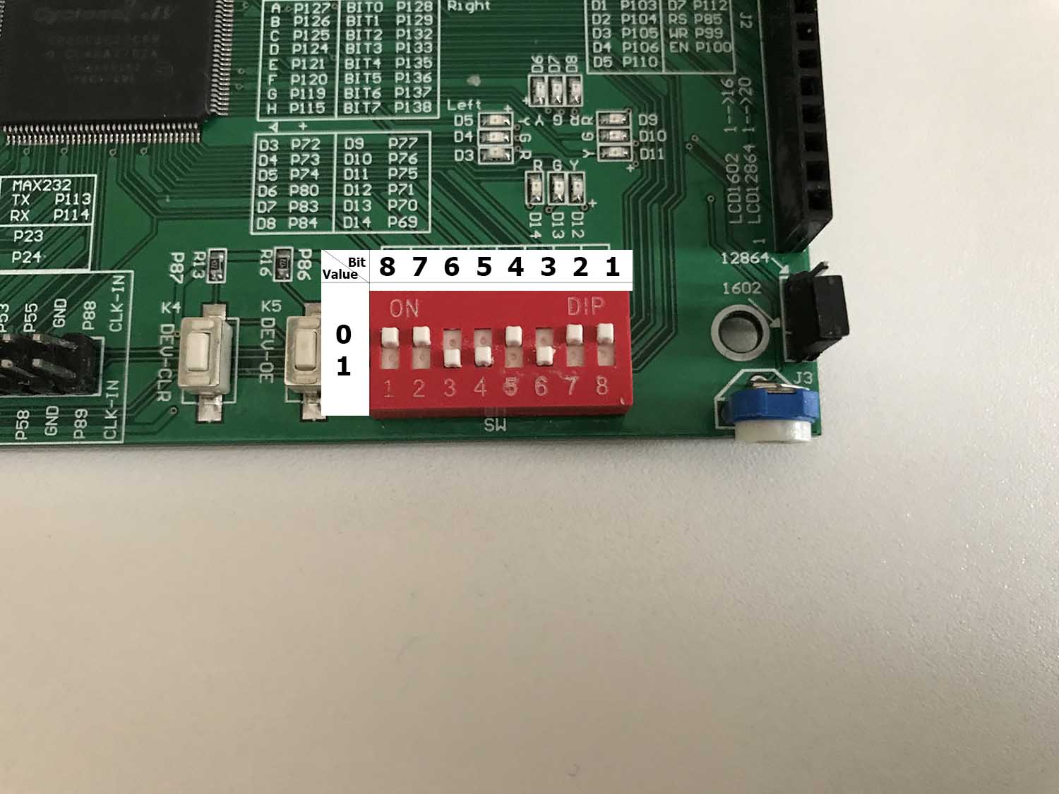
Maximum value of a number is 255, minimum — 0.
There already exists algorithm in a book Hacker«s Delight which can calculate cube root (code is on Java):
public int cube_root(int val){
int s = 0;
int y = 0;
int b = 0;
for (s=30;s>=0;s=s-3){
y = 2*y;
b = (3*y*(y+1)+1) << s;
if (x>=b){
x = x-b;
y = y+1;
}
}
return y;
}
But it can only output integer results. In order to overcome this restriction we need to multiply our input value on 10^(3*n), n — natural number, and then split results into digits. Our n last digits will be fractional part. I decided to show results with 2 digits after point. It means that we need to multiply input value on 1 000 000.
Here is the code on Verilog:
// Calculating cubic root of number
always@(*) begin : block_0
reg [31:0] x;
integer s;
integer y;
integer b;
integer i;
x = number;
x = x * 1_000_000;
y = 0;
for (s=30;s>=0;s=s-3)
begin : block_calc
y=y*2;
b = (3*y*(y+1)+1) << s;
if (x>=b)
begin : block_1
x = x-b;
y=y+1;
end
end
result1 = y / 100; // First digit
result2 = (y % 100)/10; // Second digit
result3 = y % 10; // Third digit
end
The whole code of my project:
module cube_root(
input clk, // Clock signal 50Mhz
input [7:0] number, // Input value
output reg [3:0] Anode_Activate, // Setter for activating segments
output reg [7:0] LED_out // Value on the segment
);
reg [4:0] result1; // First segments's value
reg [4:0] result2; // Second segments's value
reg [4:0] result3; // Third segments's value
reg [4:0] LED_BCD; // Current segments's value (not used)
reg [19:0] refresh_counter; // Segmens update counter
wire [1:0] LED_activating_counter; // Segment activation counter
// Calculating cubic root of number
always@(*) begin : block_0
reg [31:0] x;
integer s;
integer y;
integer b;
integer i;
x = number;
x = x * 1_000_000;
y = 0;
for (s=30;s>=0;s=s-3)
begin : block_calc
y=y*2;
b = (3*y*(y+1)+1) << s;
if (x>=b)
begin : block_1
x = x-b;
y=y+1;
end
end
result1 = y / 100;
result2 = (y % 100)/10;
result3 = y % 10;
end
// Changing refresh_counter to update segments
always @(posedge clk)
begin
refresh_counter <= refresh_counter + 1;
end
// Setting LED_activating_counter as 2 last bits of refresh_counter
// in order to update segments each 5.2 ms
assign LED_activating_counter = refresh_counter[19:18];
// Setting one segment activated accorfing to LED_activating_counter
always @(*)
begin
case(LED_activating_counter)
2'b00: begin
Anode_Activate = 4'b0111;
LED_BCD = result1;
LED_BCD[4] = 1; // This bit is responsible for showing dot
end
2'b01: begin
Anode_Activate = 4'b1011;
LED_BCD = result2;
LED_BCD[4] = 0;
end
2'b10: begin
Anode_Activate = 4'b1101;
LED_BCD = result3;
LED_BCD[4] = 0;
end
2'b11: begin
Anode_Activate = 4'b1110;
LED_BCD = 5'b01011;
end
endcase
end
// Setting value for activated segment
always @(*)
begin
case(LED_BCD)
5'b00000: LED_out = 8'b00000011; // "0"
5'b00001: LED_out = 8'b10011111; // "1"
5'b00010: LED_out = 8'b00100101; // "2"
5'b00011: LED_out = 8'b00001101; // "3"
5'b00100: LED_out = 8'b10011001; // "4"
5'b00101: LED_out = 8'b01001001; // "5"
5'b00110: LED_out = 8'b01000001; // "6"
5'b00111: LED_out = 8'b00011111; // "7"
5'b01000: LED_out = 8'b00000001; // "8"
5'b01001: LED_out = 8'b00001001; // "9"
5'b01011: LED_out = 8'b11111111; // " "
5'b10000: LED_out = 8'b00000010; // "0."
5'b10001: LED_out = 8'b10011110; // "1."
5'b10010: LED_out = 8'b00100100; // "2."
5'b10011: LED_out = 8'b00001100; // "3."
5'b10100: LED_out = 8'b10011000; // "4."
5'b10101: LED_out = 8'b01001000; // "5."
5'b10110: LED_out = 8'b01000000; // "6."
5'b10111: LED_out = 8'b00011110; // "7."
5'b11000: LED_out = 8'b00000000; // "8."
5'b11001: LED_out = 8'b00001000; // "9."
default: LED_out = 8'b00000000; // "8."
endcase
end
endmodule
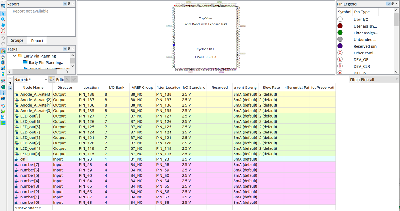
Pin assignments.
Now, I have to specify which pins will be connected with declared ones in module. We can do it in pin planner:
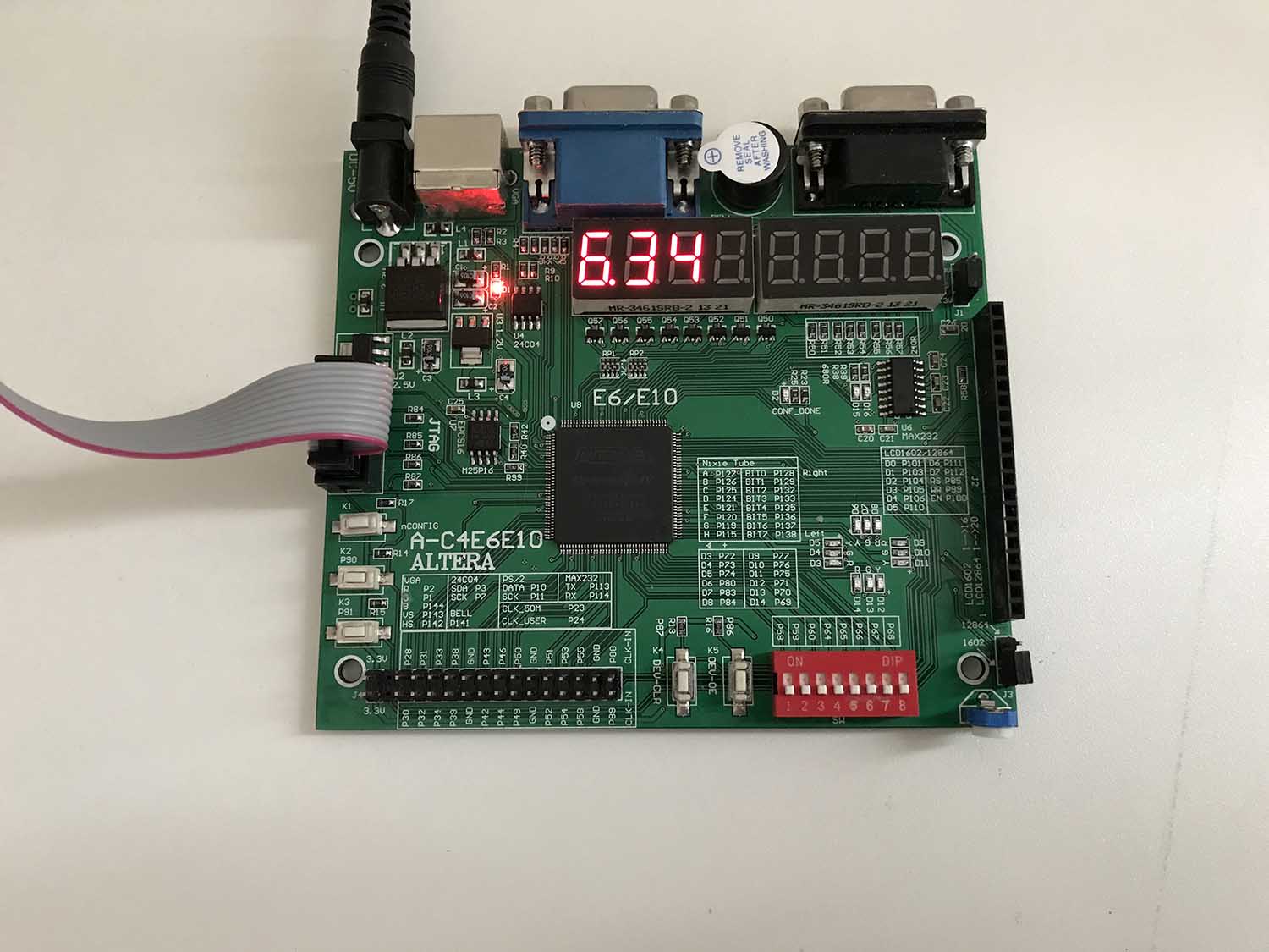
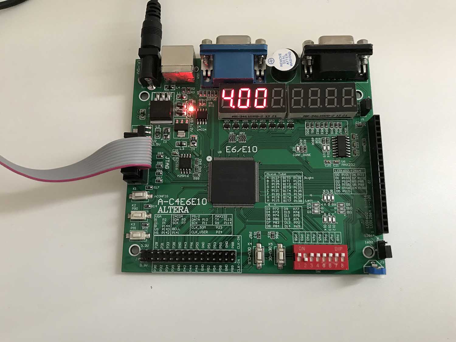
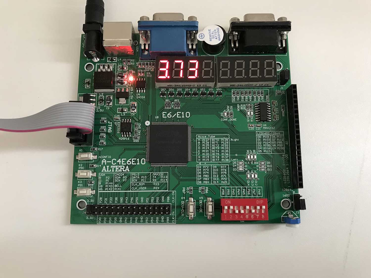
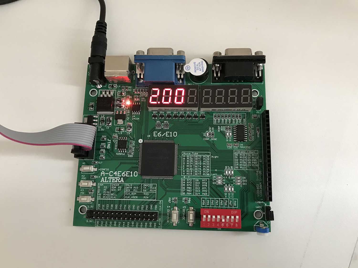
Results of our work.
After compiling our project we can run it on FPGA. Here are photos with results of a program:
Useful links:
Lesson on how to deal with 7-segment display on Cyclone IV- [FPGA Tutorial] Seven-Segment LED Display on Basys 3 FPGA — FPGA4student.com
Algorithm for calculating cube root on C — Пролистал 2-е издание Hacker«s Delight в поисках занятных задач для лабника по Verilog & FPGA — Silicon Russia & Ukraine (silicon-russia.com)
