Ternary computing: basics
I am working on a computer architecture principles lectures for our university; and as an assignment I’d like to propose to my students to build a simple programmable machine working in ternary. The main reason is fun: as a lecturer I must bring a bit of entertainment, otherwise I won’t be listened to. Besides, it is important for historic reasons. Any further «why?!» questions will be answered «Because I can».
This page describes the very basics, it won’t go beyond a simple ternary adder (and its hardware implementation). Stay tuned for more.
I chose the balanced ternary system: every trit represents one of three possible states, -1, 0 or 1. A very extensive description of this system may be found here.
Abstraction
The only block that will be used in my computer is the ternary multiplexer.
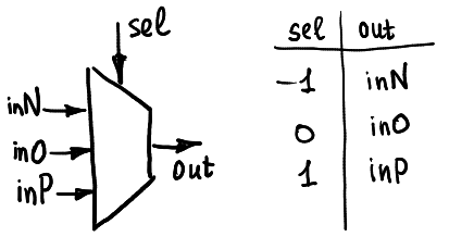
It can be seen as a black box with five pins: the selector pin receives a ternary signal (either -1, 0 or 1), and then there is a little switch inside the box that connects the output pin with one of three input pins inN, inO or inP.
Usually it is depicted as shown here:
Ternary demultiplexer works in the similar way: depending on the selector pin one input is connected with one of three possible output pins. Note that in my hardware I use CMOS analog switches. Those are bi-directional, so the hardware can be used both as multiplexer and demultiplexer. But anyways, for now I do not use demultiplexing possibilities.
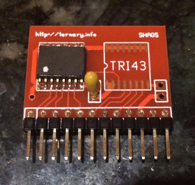
Hardware implementation
The basic design was proposed by Shaos.
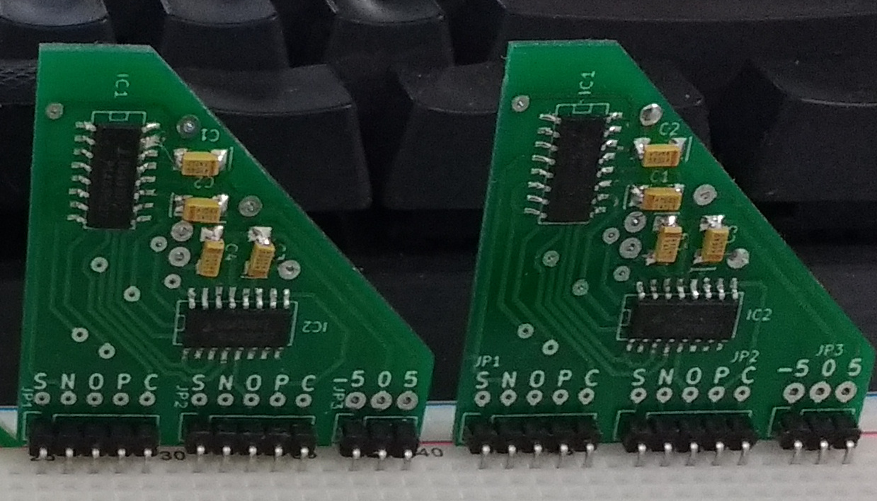
The only thing I did is to create SMD version of the TRIMUX. Surface mount dg403 switches can be bought for 50p per piece in China.
Before I found this design I tried to use combinations of cd4007 and cd4016. It worked, but the hardware is cumbersome and ugly. DG403 switches provide true ternary computing possibilities without any redundancy like to use two-bit binary and ban one of four configurations.
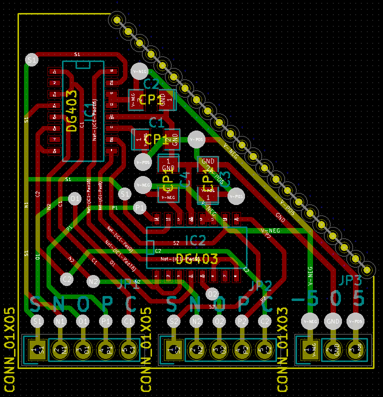
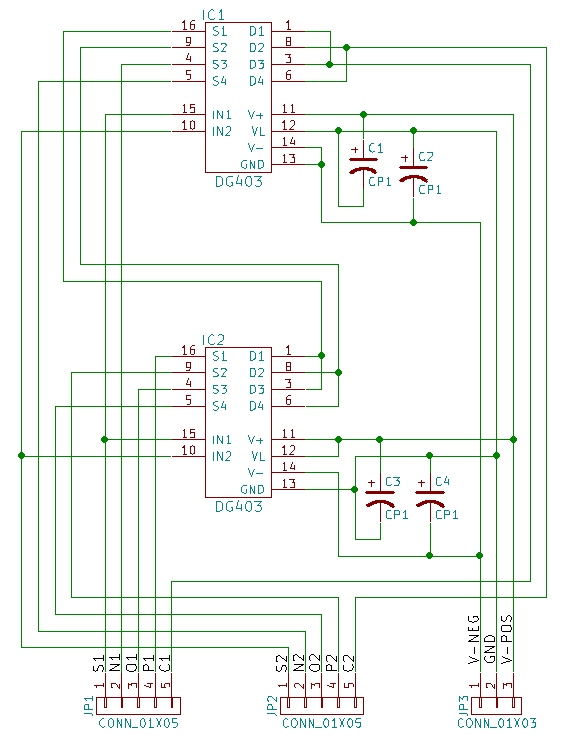
One ternary multiplexer can be created with two DG403: one of the ICs receives -5V to 0V power input, while the other one is powered with 0V to 5V, and it allows use ternary signals represented by three tensions -5V, 0V and 5V, respectively. This design uses only half of dg403 pins, therefore it is natural to create a board with two multiplexers.
Do not hesitate to contact Shaos here. Amazing guy, instead of speculating about benefits of the ternary, he designed and fabricated his own ternary ICs!
Let us omit the identity function that we can obtain by giving -1,0 and 1 to corresponding input pins of the multiplexer.
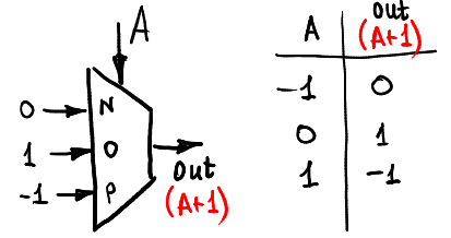
For the beginnning let us increment input signal A by computing A+1 (of course, in the -1,0,1 ring):
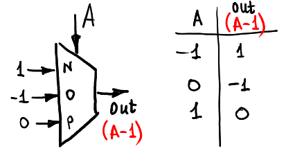
Here is the way we can decrement the input:
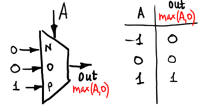
Let us compute max (A,0):
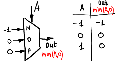
And the min (A,0):
A+B
So, one multiplexer allows us to compute any unary function. To compute a function of two arguments we need to use three or four multiplexers. For example, if we want to compute a sum of two signals A and B (still in the ring -1,0,1), then we can use this schema:
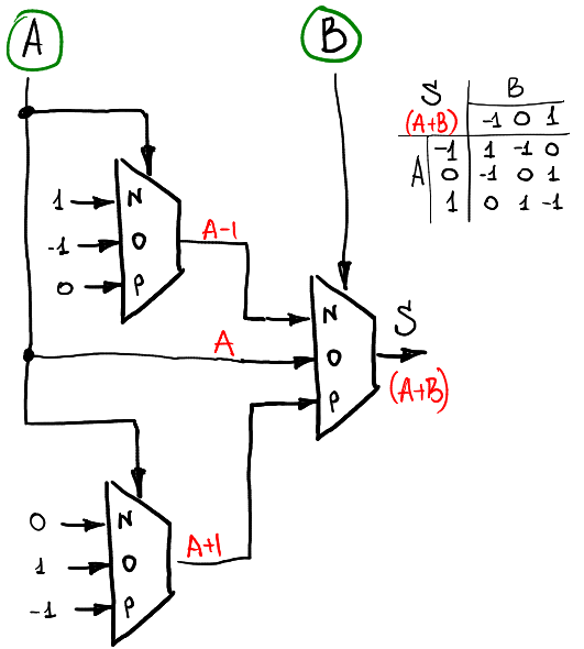
There are two layers of multiplexers: the first one computes unary functions of A, and the second layer combines them in accordance with B.
Consensus
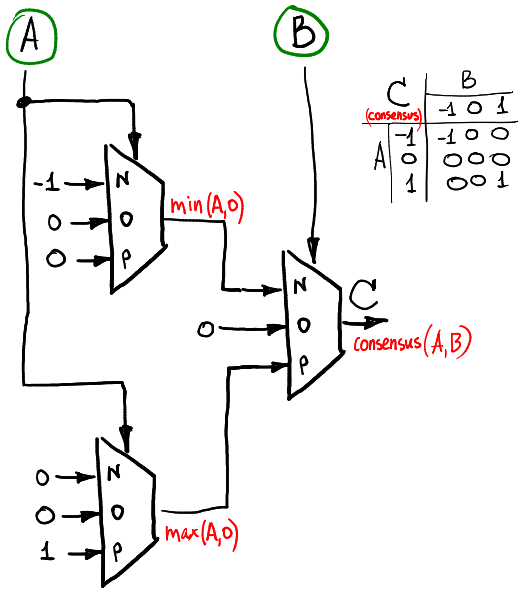
If we want to compute consensus function of two ternary signals (consensus equals -1 if A=B=-1, equals 1 if A=B=1 and is zero otherwise), then we can do it like this:
Hardware implementation
In fact, we just created a half-adder. For two inputs A and B it computes two outputs S and C related as A + B = S + 3*C. S is the sum and C is the carry flag.
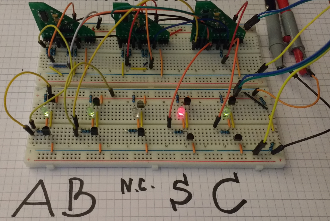
Let us test the design! Red LED means -1, off means 0, green LED means 1. Thus, this photo tells us that S=-1, C=1, or, in other words, 1+1 = -1 + 3×1:
Here is the table that lists all nine possible states of our half-adder. Each cell gives corresponding values for S and C. A link to a photo is provided for each cell.
| S, C | B | |||
| -1 | 0 | 1 | ||
| A | -1 | 1,-1 | -1,0 | 0,0 |
| 0 | -1,0 | 0,0 | 1,0 | |
| 1 | 0,0 | 1,0 | -1,1 |
In the contrast with the half-adder, a full-adder receives three inputs A, B, Cin and computes two outputs S and Cout related as A + B + Cin = S + 3*Cout.
Sum of three trits
If we want to compute a sum of A+B+Cin, the idea is the same as before: we use layer-by-layer preparation of inputs. The first layer receives A as an input, the second uses B and the last single-multiplexer layer uses Cin. Here is one possible way to compute the output S:
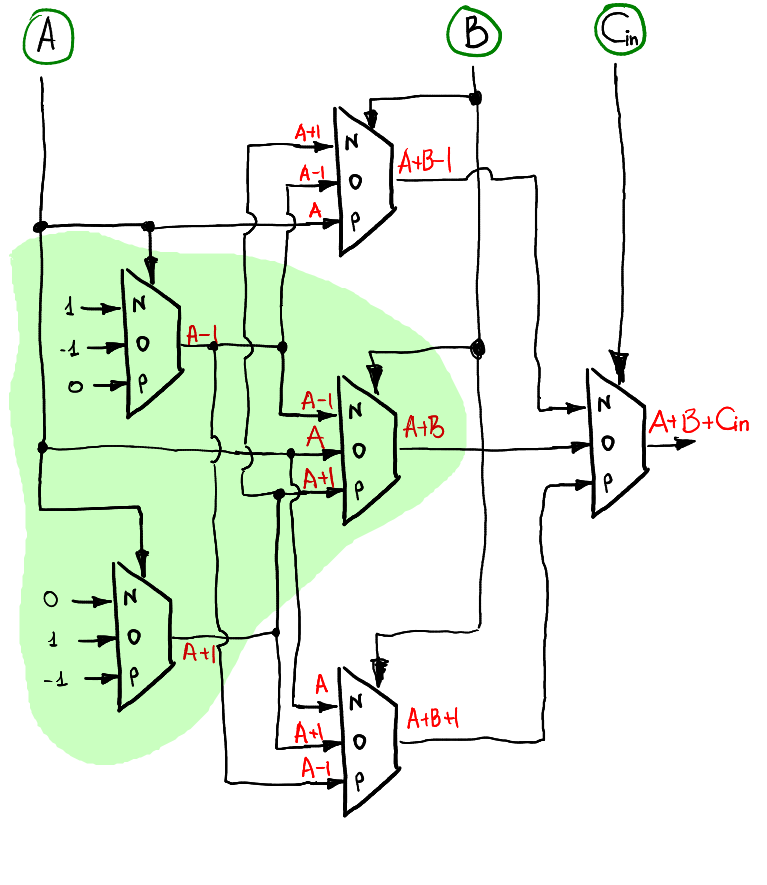
Note that when Cin=0, it behaves exactly in the same manner as the half-adder, therefore it is natural to see the inclusion (highlighted in green) of the half-adder schematics in the full-adder.
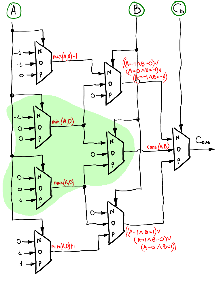
Overflow (carry flag)
The overflow trit can be computed in the same layer-by-layer way. It is also includes the half-adder!
Hardware validation
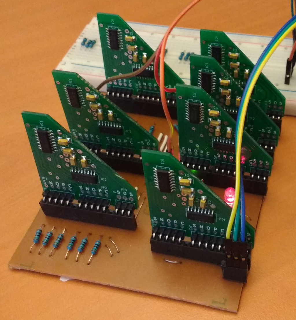
This time I was too lazy to use breadboards to test the full adder, so I made this one layer PCB:

Here it is after the copper was etched:
Three following tables list all 27 possible states of the full-adder. As before, the photos are available for each state. Note that the middle table (Cin=0) is exactly the same as for the half-adder.
The advantage of the full adder with respect to the half-adder is the possibility to stack multiple adders until we get enough trits to represent the number we want.
Here is a stack of two adders:
And here how it solves -4 + 2 (the least significant trit is on the left): 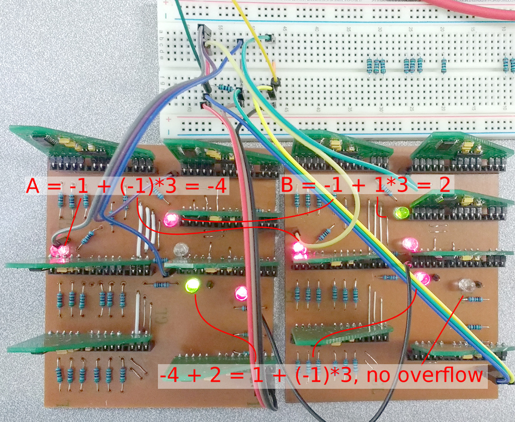
Of course, we do not need a full adder board for the least significant trit (we do not have carry flag for the input of the least significant trit), half-adder would suffice.
This is the end of the introduction to ternary computing. Stay tuned for clocks, counters, memory and more!
